Lone Star Magnum with NUM Controller
PypeServer for the Lone Star Magnum with a NUM Controller
This document covers topics specific to PypeServer output for Lone Star machines running NUM controllers.
Topics in this document:
PypeServer settings for creating NC Code (.xpi files) for the machine
NC file monitoring for PypeServer part cut status
Various methods for nesting in the pipe dead-zone
This document does not cover operating the machine controller UI that is provided by NUM.
Other recommended documents:
Getting Started with PypeServer (document) covers setup and use of the system for users and IT.*
NC File Management and Sync (video)*
Documentation provided by Lone Star or NUM covering:
The .xpi numerical control language
NUM machine application (HMI) use
Machine operation
Using the FX Simulation application which can both simulate running an .xpi file, and can show the machine running live.
*This training content can be found in the PypeServer Training app or in the PypeServer Enterprise applications "Training" tab
Table of Contents
2 Numerical Control File Output as .xpi files 3
2.1 Sending a .xpi Cut a Program to the Machine 3
3 PypeServer Machine Settings for Creating .xpi Files 5
3.2 "Machine Zero to End of Pipe" and "Using Pipe End Stop" for Using Pipe Far End 6
3.3 Folder or IP Address = <Shared folder> (where the NC files are sent) 6
3.4 NC (.xpi) PypeServer Part Status Synchronization 7
3.5 Add Date Time to NC File Names 8
3.6 Limit Roller Bed Rotation Range 9
3.7 Pause After Pieces Shorter Than <machine units> 9
3.8 Return to Start After Final Cut and Pause Before Returning to Start 10
3.10 Stagger Straight Cut Start Rotation Dist = <distance> 12
3.11 Other Machine Settings 12
3.12 Is Metric = <checkbox> 13
4 Last Cut on End of Pipe "Use Far Pipe End" 13
5.2 Max Bevel Angle U and Max Bevel Angle V 17
5.4 Cut Height and supporting Settings 18
5.5 Dynamic Torch Height Control 18
5.6 Height Sensing Settings 18
5.7 Lock Pipe Rotation On Holes 19
5.9 Torch Start Dwell Secs (seconds) 19
Machine Type
This document covers settings for machines with the following characteristics:
NUM controller
NUM Flexium HMI and NUM Flexium 3D simulation tool
Rollerbed for pipe rotation (instead of a chuck)
ImaTecno A-B torch beveling head (instead of a tilting head or pantograph)
Numerical Control File Output as .xpi files
For machines with a NUM controller, PypeServer outputs .xpi files that are g-code to be run by both the machine and the simulator.
Sending a .xpi Cut a Program to the Machine
Per the diagram below, PypeServer writes .xpi files to a folder location that the machine can also access. In PypeServer application this location is set in machine settings. See the Folder or IP Address section for more information.
The folder location can be a shared file on the PypeServer computer, the Lone Star machine, or anywhere that both computer and machine can access read/write. This is commonly set up by your IT department or anyone with rights to create a network folder share.
The diagram shows the overall topology of PypeServer products. The area in the red rectangle shows where PypeServer writes .xpi files out to a shared folder. These .xpi files are then loaded by the machine controller app (the NUM HMI). In this example the folder is on the actual Machine computer.
PypeServer Machine Settings for Creating .xpi Files
This section covers the settings in PypeServer that affect machine behavior via .xpi program files. The settings NOT highlighted are either set by PypeServer, or adjusted as needed per customer support. This dialog is opened through Settings ?? Machine Settings tab.
If you have multiple machines on the same server, you'll need to be sure to select the correct machine. If you are at the PypeServer machine kiosk where the server is running, you will have rights to modify some of these settings. For some settings, or when on a remote computer (not at the machine), you will need to enter the Admin password, which by default is "Admin". This password can be changed per request.
Cutting Dead Zone
This is the distance that you do not want the machine to cut at the far, final end of the pipe. Considerations for a dead zone include the position of the ground inside the pipe and also the wheels supporting the far end of the pipe. Note that if you make this distance less than the distance between two wheel-sets, the remaining drop pipe will likely tilt up or down when the final endcut is made.
It is also possible to use the far end of the pipe as the final endcut of a part, thereby using the entire pipe. When using the far end of the pipe as the end of a part you STILL should have a dead-zone so that no cuts are placed in the dead-zone. Please see the section Last Cut on End of Pipe for more information.
"Machine Zero to End of Pipe" and "Using Pipe End Stop" for Using Pipe Far End
Please see the section Last Cut on End of Pipe for more information.
Folder or IP Address = <Shared folder> (where the NC files are sent)
This is the location that the .xpi files are written to. This can be any folder that the machine can locate and load .xpi programs from. Note that if you load files from a PypeServer remote seat, you will need to use a share name that resolves to the same folder for any computer that is running PypeServer and outputting .xpi files. For example a network share like \\LoneStarMachine\PypeServerFiles or \\PypeServer\MachineOutput, or a share on each computer that is mapped to the same drive letter for all PypeServer computers that write output.
Note that if you use network drive mappings (such as z:\), and then change the drive letter, then the cut status synchronization system will not work for previous files in process.
See also Sending a .xpi Cut a Program to the Machine and NC (.xpi) PypeServer Part Status Synchronization.
NC (.xpi) PypeServer Part Status Synchronization
This section discusses how PypeServer can monitor .xpi files to maintain the status of scheduled parts. Scheduled Part status can be:
Not Nested
Nested
On Machine
Cut
Scrapped
This synchronization behavior is summarized in the following diagram:
For more information, please see the PypeServer training video "NC File Management and Sync".
There are three parameters involved in this process:
Data Reporting Mode
Computer Watching Files
NC File Timer Interval Seconds
Data Reporting Mode = SystemWatchesFiles : With this setting, PypeServer will monitor the "Folder or IP Address" folder, such that
When files are deleted, the Scheduled Parts' status are changed from "On Machine" to "Cut".
When files are move to the subfolder "Return To PypeServer Nested", the Scheduled Parts' status are changed from "On Machine" to "Nested"
When a user in PypeServer changes a pipe nesting that is currently "On Machine" back to nested, the NC (.xpi) file will be deleted. This is done so that operators do not cut parts that are not ready to be cut.
Data Reporting Mode = None (Manual)
With no data reporting (file tracking), users will need to manage the status of pipes after they are cut.
If this mode is selected, then the user can (should) maintain Scheduled Part cut status in PypeServer by selecting one or more pipes and selecting the Change Status button as shown here:
Note that this extra work is performed automatically when Data Reporting Mode = SystemWatchesFiles.
Other Data Reporting Mode settings are not applicable for this machine
Computer Watching Files
This is the name of the computer that is watching files in the NC folder location (Folder or IP Address) for changes to the file's existence. This is typically the name of the computer with the PypeServer SQL server that is typically near the machine. By default this computer name is PYPESERVER.
NC File Timer Interval Seconds = <minutes>
When you use this synchronization feature, you can set how often the system checks the NC file folder for synchronization. This setting is in the System Properties Tab and is a global setting for all machines, shown here:
For more information, please see the training video "NC File Management and Sync".
Add Date Time to NC File Names
Set to true and the date will be appended to the file name. For example:
Add Date Time To NC File Names:
False: "Part 138.xpi"
True: "Part 138 Apr 18-24 2.35 PM.xpi"
Notes
Using this feature can result in duplicates if the operator makes changes to a part or pipe nesting and creates a new .xpi file.
This feature is not recommended when using "System Watches Files" part status synchronization, as multiple files for the same part become monitored.
Limit Roller Bed Rotation Range
This section is important for cut accuracy!
PypeServer will automatically rotate the pipe the shortest direction to advance to the next cut. With numerous cuts placed in sequence around the pipe, the pipe will rotate to each cut in one direction for multiple rotations. If the machine is using the roller bed wheels to roll the pipe (instead of a chuck) then any inaccuracies in the actual pipe diameter will accumulate with each rotation. For example if you enter a pipe diameter that is off by 0.1", then each pipe rotation will make subsequent cuts off by .314". So, if the pipe is rotated 4 times, holes cut at the same rotation around will actually be off 1.25" from first hole to last hole. To prevent this:
Set the "Limit Roller Bed Rotation Range" to somewhere between 1.5 rotations (540 degrees) and 3 rotations (1080 degrees). The downside of a tighter range is that the machine will not take the fastest rotation to the next cut, but instead will "unwind" back toward zero.
Get your pipe diameter exactly correct. If cutting holes, saddles or miters, it is not enough to enter the nominal pipe OD if the pipe is not in fact nominal in size. Note that pipe diameters vary around the pipe, so measuring in more than one point across is important.
Measuring Hint: One way to more accurately measure the pipe diameter is to wrap a piece of thin string (dental floss for example) 4 times around the pipe and cut the string to the exact length where the string started. Then measure the distance of the string (without stretching it) and divide by 4*Pi, which is (12.56637). Operators are often surprised at the difference between this and the diameter they measured across the pipe.
Pause After Pieces Shorter Than <machine units>
Small parts, including the thin waste pieces between nested parts can fall into the wheel-bed or get tangled up with the pipe being cut. You can instruct the machine to pause when a piece or waste piece is shorter than a given length (in machine units). The machine will not pause when this setting = Zero.
Why make this longer than, say 4 inches? Parts or the remaining drop piece can also rock/tilt up or down if resting on only one wheel-set. For example if the distance between rollers is 24" and a 40" part was cut with the first cut being 23 inches away from a roller set, then the part would rock on the wheel set and the end just cut would lift up into the torch, probably causing a fault.
If this rocking is a concern, then set the Pause After Pieces Shorter Than to 2 times the distance between wheelsets. The rocking may still occur, but the machine will stop after the cut for you to check that everything is OK.
Return to Start After Final Cut and Pause Before Returning to Start
With "Return to Start After Final Cut" = true, instructions will be added in the .xpi file to return the machine to its original X location after the program is finished.
Set "Pause Before Returning to Start" = true if you want the machine to pause before returning to the start after the final cut.
RTCP Compensation
RTCP Compensation is explained below. The PypeServer Enterprise tool for calculating RTCP compensation is discussed after this explanation.
For accurate bevel cutting it is critical to have the proper length between the pivot axis B and the tip of the torch. Per the diagram below the following settings must be set correctly:
Original RTCP height. This is set by Lone Star at machine commissioning.
RTCP Compensation. This is zero from the factory, but if the torch is moved up or down in its collar, then that height will need to be compensated using the RTCP Compensation setting. The torch could also be adjusted back to zero, but the accuracy required for this (to make accurate cuts) makes it difficult to manually shift the torch to the exact desired location.
This is the height of the shield. When the user changes to a shield tip of a different length, they need to enter the new shield height.
Desired Cut Height. Note: Torch providers often specify cut heights that work for flat plate, but are unrealistically low for cutting rolling pipe. Especially rolling pipe that is not exactly round or has seams.
The RTCP Offset (Compensation) Tool
PypeServer provides a tool in the Enterprise application to assist you in getting the RTCP height correct. This tool requires that you cut short sample coupons, measure them and enter the resulting measurements in the tool. In Settings ?? Machine Settings, follow the directions provided in the tool.
Stagger Straight Cut Start Rotation Dist = <distance>
When straight cuts are nested together without any rotation between starts and finish, the leadins and leadouts can overlap and cause the torch to burn incorrectly (gap sideways), or fault as the leadin cut hits the previous cut's leadin and leadout gaps. This setting instructs PypeServer nesting to rotate the next part by a distance (around the pipe) so as to avoid this intersection. Shown below is a 4.5" pipe with StaggerStraightCutStartRotationDist = 1 inch.
Other Machine Settings
LeadIn/Out Settings
These settings are seldom changed. These are only limits. The actual leadin settings are made in the Torch settings, but they must fall within these limits.
For more information, please see the document "Torch End of Cut Leadout and Tuning" in the PypeServer training system.
Leadin Min Distance = <distance>
This is the minimum distance allowed for a leadin in PypeServer.
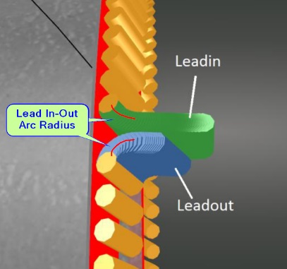 Lead In-Out Arc Radius = <distance>
This is the radius of the turn made by the leadin. Note that this is not the overall length of the leadin. Having this as a small radius decreases the range of gouging, but the tradeoff is that if it's too tight, the machine may fault, have difficulty making turn smoothly, or the pipe may slip on the rollerbed wheels.
Leadin Steps = <integer number>
This is the number of steps PypeServer creates for the leadin. This adjustment is not typically made by the user.
Is Metric = <checkbox>
If you set this to Metric, all your machine and torch settings will be interpreted as metric. You can still create and cut parts and nestings designed in standard (Imperial) units. Note that you do not need to set this to Metric just because your machine runs in metric. This is only a convenience to allow users to work in familiar units.
Last Cut on End of Pipe "Use Far Pipe End"
PypeServer can cut single parts and also nest parts to use the far end of the pipe as the final (straight) cut of the last part. This allows PypeServer to nest through the Dead-Zone-where the ground is located, but not make any actual cuts in that Dead-Zone. To use this feature:
One-Time Setup:
Set the Machine Cutting Dead Zone.
Set Using a pipe end-stop to indicate how the machine (torch) starting position is determined to be the correct distance from the far end of the pipe.
Using a pipe end-stop = True
If your machine can be zeroed down the gantry travel (X), then you can add a fixed end stop where the pipe is stopped every time when loading. This stop can be on either end of the pipe. Using an end stop (with the settings discussed here) will allow the machine to automatically move to a starting position that will make the far end of the pipe the final cut for the last part.Set your Machine Zero to End of Pipe. This tells the machine where the end of the pipe is located at the end-stop.
Place the pipe against the end-stop
Zero the machine,
Jog down the pipe (X) to where the edge of the pipe runs across the torch centerline.
Enter the gantry position (X) value in "Machine Zero to End of Pipe".
Manually measuring the starting point from the end of the pipe: set "Using Pipe End Stop" to false. If you do not use an endstop, the .xpi code will provide a distance down the pipe from the far end that the torch must be started so that the far end is the final cut.
To nest in the dead-zone and use the far end of the pipe, for each pipe:
Check the "Use Pipe Far End" on the Pipe. Checking this will change the Dead-Zone indicator to green and PypeServer will nest parts into that zone.
By default, PypeServer will not nest cuts in the dead-zone, but it's still good practice to make sure no cuts are in that zone. Note that you can allow cuts in the dead-zone by checking "Allow Cuts in the Dead Zone". These dead-zone cuts will be added to the program but the machine will pause before making these cuts.
Here's one example of nesting with the Use Far Pipe End checked:
Note: You can also set these as default settings for new pipes in the Nesting Settings dialog:
Note: when not using the far pipe end ("Use Far Pipe End" unchecked), then this dead-zone will show up in PypeServer as a yellow area on the end of the pipe and PypeServer will not nest into it. It will look like this:
Plasma Torch Settings
This section covers plasma torch settings that operators typically need to understand and adjust. The settings NOT highlighted are either common to other training content (such as Kerf and Leadin), are set by PypeServer, or are adjusted as needed per customer support. This dialog is opened through Settings ?? Machine Settings tab.
Some machine (torches) can also be set to etch mode. There is a separate "Torch" for etching.
Tools
Calculate Cutter Kerf
This tool will help you calculate the plasma kerf (cutter width) by cutting a sample part. It will also help you calculate torch beam divergence (see Beam Divergence in the Training docs). For straight cuts and thin-walled pipe, you do not need to change beam divergence. Beam Divergence should be set correctly if you are cutting steep bevels on thicker pipe.
RTCP Offset Tool and RTCP Offset Setting
See the RTCP Compensation section in Machine Settings
Torch Controller
If you are using a torch controller, you can access the Torch Controller settings here. Torch Controller settings are covered in a separate document TBD.
Max Bevel Angle U and Max Bevel Angle V
These define the maximum bevel that the torch should make for a cut. This is not a machine limitation, but is the limitation imposed by the torch tip's ability to tilt and still cut well, without having to lift back too far away from the part. Numbers typically range from 40-50 degrees of tilt over from straight up and down.
Pause for Torch Change
Most torches cannot automatically change from Cut to Mark (Etch). Users can still create parts with both Plasma cuts and Etch marks, but will need the machine to pause when the torch needs to switch between cutting and etching. For both Plasma and Etch torches, check the Pause For Torch Change setting.
Note: For cutting parts with etching you can order all your etches first so that the machine only pauses once to change from etch back to cut mode. For cutting pipe nestings, you can also reorder cuts for the entire nesting so that etches all occur first. However if something goes wrong when cutting a part, you may have etches in the wrong places after recovering or restarting.
Both Plasma and Etch torches must be configured to Pause for Torch Change.
Note: The machine will not pause for torch change on the first cut. If your first "cut" is an etch, you will need to have your torch set up for etching.
Cut Height and supporting Settings
Settings:
Cut Height
Tip Edge Min Interference Distance
Torch Tip Base Diameter
Cut Height is the height the torch should maintain off the pipe. This is measured from the center of the hole of the torch to the pipe. This height is maintained when beveling unless height limits are reached.
When beveling, the edge/side of the torch tip will move closer to the pipe then the center of the torch tip. The "Tip Edge Min Interference Dist" setting defines the minimum height allowed for the edge of the tip.
To calculate the location of the tip edge, the system relies on the "Torch Tip Base Diameter" setting. When the bevel becomes steep enough that the torch tip will be less than the Tip Edge Min Interference Dist, the torch will shift up along the torch axis to maintain the required minimum height.
Things to consider when setting this minimum height includes the height of pipe seams, and if you are using voltage Height Sensing. Voltage Height Sensing can be unreliable when beveling. Increasing this minimum height may allow cuts without using voltage Height Sensing.
Dynamic Torch Height Control
When this is true, PypeServer will dynamically calculate torch heights when the torch is beveling-raising the torch height up the torch axis as the torch bevels steeply. This is effective for hole cutting to prevent the tip from dragging on the pipe. This is often used in place of arc voltage "Height Sensing".
Height Sensing Settings
Voltage Height Sensing can be used for both end cuts and holes. They are separate because it is often less effective for holes. It is needed for endcuts when cutting larger pipe that is not perfectly round. With Height Sensing, the torch can stay a proper distance away from the pipe as it cuts higher and lower sections.
Height Sensing For Endcuts and Height Sensing for Holes
Set either or both to true to use Voltage Height Sensing. For holes, Dynamic Torch Height Control often works better.
Height Sensing Delay Before Averaging (milliseconds)
This is the amount of time from the start of the cut until the machine begins gathering height sensing voltages. This is typically after pierce and near the end of leadin. This time is required for voltages to settle to consistent values.
Height Sensing Averaging Delay (milliseconds)
This is the time of cutting for the machine to average the voltage before actually using height sensing to set torch height. This timer starts after the Height Sensing Delay Before Averaging time expires.
Lock Pipe Rotation On Holes
Set Lock Pipe Rotation On Holes to true to prevent pipe rotation when cutting smaller holes. Cutting without rotating the pipe typically results in better cuts. The size of the hole that be cut this way is limited to how far the torch can travel down Z around the pipe. This height is set by the Machine Property "Max Z Drop Over The Pipe". Warning, this value is set to negative 1 inch and represents how far the torch beveling head can drop down (when steeply beveling) before it hits the pipe. Setting this to a larger negative number may cause the head to crash into the pipe.
Torch Shield Height
This is the height of the shield you are using. If you change tips to one of a different height, you MUST change this setting to maintain beveling accuracy. See the RTCP Compensation section for more information.
Torch Start Dwell Secs (seconds)
Some torches detect when pierce has occurred. For those that don't, such as the PowerMax 125 or MaxPro 200 you will need to set this dwell time for the torch to achieve pierce after turning on. This field is typically overridden when using torch controls (if the torch control data provides this value).
Transfer Height
The height of the torch when moving before and after running the program.
Z pierce Height
The height of the torch when piercing. This is commonly greater than cut height.
Z Retract Height
The height for the torch to retract off the part between cuts.
Use Torch Control
Set "Use Torch Control" to true to use the torch control data. When using torch control, part designers and machine operators can select cut processes for Parts and Pipe Nestings. These process selections will be looked up when creating .xpi files to replace various cut and torch settings such as feedrate, kerf, cut height, pierce height, and torch start dwell. Using torch controls is covered in other documentation (TBD).
Related Articles
Lone Star Revolver with a NUM Controller
Lone Star Revolver with a NUM Controller PypeServer for the Lone Star Revolver with a NUM Controller This document covers topics specific to PypeServer output for Lone Star Revolvers with chucks, running NUM controllers. Topics in this document: ...Enterprise v4.3 Change List
General New Features CodeMeter updates now run in unattended mode for organizations that manage their software deployments. Fixes Change release note links to point to documents on Support Site Unable to nest part on a new pipe from the Design Tab ...Enterprise Training - Machine Operation
Make a single cut on the pipe Trim the pipe with a single Miter cut. Click a button when you need to make a single straight or miter endcut on the pipe. v2.16 13 Beam Divergence Beam Divergence defined and how to set What beam divergence is and how ...Enterprise v4.5 Change List
General New Features Parts Viewer New look and feel Front/Back/Isometric and Draft views Assembly Viewer - Parts tab 3D spool view of cut parts Printable Assembly Report with BOM Individual remote seat licenses are no longer required New training tab ...Enterprise v4.1 Change List
General New Features Expose Right and Left cut end notes as individual columns in the Scheduled Parts Tab Allow a remote user to bypass the folder access denied message on app startup Add Parameter to Rectangle cut so bevel is against part instead of ...