NC Code for Vernon Machines
PypeServer for Vernon Machines
This document covers topics specific to Vernon machine working well with PypeServer. Topics include:
General network layout for using PypeServer with the machine
Vernon MPM settings and PypeServer settings for running NC Code from PypeServer
NC file monitoring for PypeServer part cut status
Various methods for nesting in the pipe dead-zone
Table of Contents
1 General overview of network layout 3
2.1 Vernon Machine settings for NC: Enable the M0 (Machine Stop) command 4
2.2 Loading and Cutting a Program 5
2.3 PypeServer Machine Settings for Creating Vernon NC Files 7
3 Last Cut on End of Pipe "Use Far Pipe End" 10
3.1 Machine Setting: Cutting Dead Zone 11
4 Shift Pipe Forward after Each Part 12
4.2 Per Pipe Setting - Required 12
4.3 Machine/User sequence after each part 13
5.3 Feedrate control adjustments 15
5.4 A and C axis feedrate control adjustments 15
5.5 Torch slowdown on tilt adjustment 15
5.6 Default Smoothing Passes and Default Smoothing Distance Machine Settings 16
5.7 Add Date Time To NC Files 16
5.8 Stagger Straight Cut Start Rotation Dist = <distance> 16
7 Pause Machine for Torch Change for Fineline torches 19
7.1 Configure Torch Settings 19
7.2 NC Code (what you will see) 20
8 Swap Ground and Touch Sensor for Final Cuts 22
General overview of network layout
PypeServer can be run from any Windows computer on a network. Users from different disciplines use PypeServer for different parts of the fabrication workflow. To allow these users access to PypeServer, the PypeServer SQL server needs to be on the company domain so that CAD programmers, Detailers, Shop Foremen and others can run the PypeServer application. PypeServer also needs to connect to the machine's NC folder with read/write access, so that PypeServer users can automatically place NC files (cut programs) into that folder.
The best configuration looks like this:
Note: Internet connectivity allows PypeServer support to assist in initial system configuration and ongoing support. PypeServer can work with your IT department to get PypeServer joined to the domain. For more IT-level information, see the PypeServer training document "Getting Started with PypeServer", section 2.
NC File use
For Vernon Machines running WinMPM, PypeServer outputs to an NC format. This format allows PypeServer to fully control machine motion and thereby enables PypeServer features such as nesting, torch beam divergence (angle), using the pipe far end as a final end-cut, shifting the pipe forward after each part is cut, and other features. (These features are discussed further in this document.)
The WinMPM user's manual provides a section on NC programming for your better understanding of the actual NC codes in the PypeServer output files.
Vernon Machine settings for NC: Enable the M0 (Machine Stop) command
In some cases, PypeServer NC programs instruct the machine to stop while running the NC program so that the user can position the machine as instructed.
Vernon Newer VMD software:
Vernon's MPM software typically comes configured with an override set to ignore the machine stop M0 command. You'll need to disable this override to enable the use of M0 for PypeServer. If you do not disable this override, the M0 commands in the PypeServer program will be ignored and the machine will not stop as instructed.
Set this to Manual
To enable M0, change the "OK-to-MOVE" variable within the VMD main screen under the controls tab. When the system is in "AUTO", M00 is ignored. In "MANUAL", M00 will be enabled. This variable must to be set prior to loading the NC file.
Enabling M0 in Older WinMPM Software
Text in italics in this section are from the WinMPM manual.
You need to uncheck the "Auto-Run" checkbox in Machine Options. Go to the Machine Options Page "Tools??Machine Options", or by pressing "F6" and then "F2"
Machine options are machine particular and will override any machine options contained in .pmp program file. A Level 1 password is required to access the Machine Options windows. Some machine options require a password higher than Level 1 to change.
The Password by default is "aaaa", though it might be different for your machine.
6.2.1.8 "Auto Run"
If the "Auto Run" option is checked it will allow an entire pipe machine program (.pmp)
to be run with "Cycle Start" switch only being pushed one time at the beginning of the
program. ?
Location in the WinMPM Manual
This information is located in the WinMPM manual.? It will be in different locations depending on which version you have.
Loading and Cutting a Program
Loading a program
In the first screen that pops up on the MPM program, you'll find a "Load NC File" button.
Select the "Load NC" button
Navigate to where the NC file is located and open the file
Read the instructions in the NC file. It will tell you where to start the torch. In normal operations this start is just in from the edge of the pipe end where cutting is starting.
Then Select the "Control Panel" button.
Note: In some older systems you cannot continue to see the NC file. Please see section Machine Can View NC File When Running.
Select a Sensor
Before starting the program, you must select the leading sensor (the sensor that will touch down on the pipe at the start of the first cut). This cannot be done programmatically so it must be done in advance of running the NC program.
Hit start
This may require hitting start a few times.
PypeServer Machine Settings for Creating Vernon NC Files
This section covers the machine parameters highlighted below. The Parameters NOT highlighted are either set by PypeServer during setup or as needed per customer needs, and in some cases set automatically set by PypeServer for the Vernon machine. These parameters are seen by opening the settings ?? Machine Settings tab and (if you have multiple machines) selecting the correct machine. If you are at the machine kiosk, you will have rights to modify these settings. If you are at another computer ("remote") you will need to enter the Admin password, which by default is "Admin". This password can be changed per request.
This field has been moved to the System Properties tab
Adjust Speed By Step Count == True if running WinMPM, False if running VMD
Older Vernon machines run WinMPM (not the newer VMD). These older machines change feedrate based on the number of steps in a cut. So if you are running WinMPM, then set this to True so that your machine will respond properly to feedrate changes.
Requires_M0_OnFirstSensorsOn
Older Vernon machines require that, after any machine stop, that another stop (M0) is inserted after the torch-down seeking sensors are turned on in the GCode (with M12). If after you hit start on the first cut, your torch turns on without first seeking the pipe using the sensors, then set this to true. Note that users must hit the start button twice on starting the program.
Folder or IP Address = <Domain file share> (where the NC files are sent)
This a common read/write file location shared between PypeServer and the Vernon MPM program. PypeServer will write NC files to this folder, and the machine operator will use MPM to open and load these PypeServer NC files. Ideally this share should map to MPM's default NC folder. Depending on network and machine/MPM configurations, this may not be possible. If not possible, feel free to contact PypeServer and Lincoln to discuss.
To set up the share on your Vernon machine computer, go to the NC folder location and share it such that PypeServer can see that folder through a mapping, such as \\VernonMachine\NC
To access this share from PypeServer, enter the mapping to the machine as shown. Warning, it is not recommended to use network drive mappings (such as z:\), because if this changes, then the synchronization system will not work. If you do use network drive mappings. Do not change the drive letter.
NC File and PypeServer Part Status Synchronization
This section discusses how PypeServer can monitor files sent out to the machine to maintain the status of scheduled parts. Scheduled Part status can be:
Not Nested
Nested
On Machine
Cut
Scrapped
For more information, please see the training video "NC File Management and Sync".
Data Reporting Mode = <selection>
Data Reporting Mode = SystemWatchesFiles : With this setting, PypeServer will monitor the "Folder or IP Address" folder, such that
When files are deleted, the Scheduled Parts' status are changed from "On Machine" to "Cut".
When files are move to the subfolder: "Return To PypeServer Nested", the Scheduled Parts' status are changed from "On Machine" to "Nested"
When a user in PypeServer changes a pipe nesting that is currently "On Machine" back to nested, the NC file in the NC Programs folder (typically out at the machine) will be deleted.
This synchronization behavior is summarized in the following diagram:
Data Reporting Mode = None
With no data reporting (file tracking), users will need to manage the status of pipes after they are cut.
If this mode is selected, then the user can (should) maintain Scheduled Part cut status in PypeServer by selecting one or more pipes and selecting the Change Status button as shown here:
Note that this is extra work that is performed automatically when Data Reporting Mode = SystemWatchesFiles.
Other settings are not applicable:
The Data Reporting Mode = Automatic is for machines directly connected to PypeServer, where there is no file transfer occurring. This is not applicable to the Vernon machine.
The Data Reporting Mode = DialogProcess selection is for manual saws.
NC File Timer Interval Seconds = <minutes>
When you use this synchronization feature, you can set how often the system checks the NC file folder for synchronization. This setting is in the System Properties Tab and is a global setting for all machines, shown here:
For more information, please see the training video "NC File Management and Sync".
Machine Can View NC File When Running = <True/False>
As of this writing, this feature has not been implemented. Please contact PypeServer for availability.
In some older WinMPM systems you cannot continue to see the NC file when running the program. In this case, PypeServer will create a second file that will provide a list of M0 commands in the program, in order. The user, when running the program, can view this list (in notepad or similar app), or print the list, and check off each M0 stop as they are reached.
Set this to False if you cannot see the NC file when running.
Machine Can View NC File When Running = False
Note that in most cases the reason for the machine pause is intuitive. One important pause is when using the feature to swap the ground and sensor to nest through the dead zone. In that case the machine must be aware of when to swap the sensor, or upon the next cut, will likely crash the torch head.
Last Cut on End of Pipe "Use Far Pipe End"
PypeServer can nest parts so as to use the far end of the pipe as the final (straight) cut of the last part. This allows PypeServer to nest "through" the "Dead-Zone"-where the ground is located. To use this feature:
One-Time Setup:
You must specify the Dead-Zone in machine settings
You must select the way that the machine knows where the far end of the pipe is located.
Each Pipe:
You must make sure no cuts go into the Dead-Zone
You must check the "Use Pipe Far End" on the Pipe. Checking this will change the Dead-Zone indicator to green and PypeServer will nest parts into that zone.
One configuration of nesting with the Far Pipe End looks like this:
Note: You can also check the Use Far Pipe End checkbox in the Nesting Settings dialog so that all new Pipes will have this checked.
Settings discussed in this section are highlighted here in Machine Settings. To see them you may need to enter the Machine Admin password.
Machine Setting: Cutting Dead Zone
When you nest with "Use Far Pipe End" checked, the dead zone will become green to indicate that you can nest in it. However, PypeServer still needs to know the Cutting Dead Zone. The Cutting Dead Zone defines the area of pipe that the torch should not cut because it will hit the ground, and should not try to touch off its height because the active sensor will be off the end of the pipe.
Cutting Dead Zone is set this to the greater value of
The distance that your ground goes into the pipe, plus enough to keep metal splash off your ground, or
The distance from the torch to the end of the pipe, when the sensor is as far to the end of the pipe as you can go. It's important to measure this sensor distance so that PypeServer does not create cuts where the sensor arm will be off the pipe.
When not using the far pipe end ("Use Far Pipe End" unchecked), then this dead-zone will show up in PypeServer as a yellow area on the end of the pipe and PypeServer will not nest into it. It will look like this:
Shift Pipe Forward after Each Part
This feature allows the machine operator to shift the pipe forward after each part is cut. This is useful in various cases, including the cutting of large, heavy parts that need to be unloaded from the end of the machine, or cutting small parts where each part can be easily dropped off the end onto a cart.
Machine Setting
To enable this feature, you must, in Machine Settings, set the "Supports Shift Pipe Forward" parameter to true.
This will cause this feature to show up as the Pipe parameter.
Per Pipe Setting - Required
Once the Machine setting is set to true, you still need to check the Pipe's "Shift Pipe Forward" checkbox, shown here:
Note: If you are shifting the pipe forward on every pipe, you can check the "Shift Pipe Forward after each part" checkbox in the Nesting Settings dialog to cause each new pipe to have the Shift Pipe Forward option automatically checked.
Machine/User sequence after each part
Here is the sequence of machine and user steps that occurs after a part is cut to resuming cutting the next part:
This sequence requires the user to hit cancel at the M0 twice, once to move the torch out of the way to remove the cut part (only if needed), and once to shift the pipe forward so the last pierce hole is under the torch.
Program finishes cutting a part.
Program moves torch Y position back to the start of last part, and moves the pipe X rotation to the pierce-hole of the last cut on last part
Machine stops with an M0
Step four is used only if the user needs to jog the torch out of the way to clear the part. If you don't need to clear the part, just press OK.
User: selects Cancel (The program is still running, but the user can jog the torch and move the pipe.)
User: jogs the torch down the carriage to get the torch out of the way
User: removes cut part
User: selects Run Program again.
Machine will return to the position before the jog in step 5.
Steps 5 and 6 are where you position the torch back over the pierce hole of the last cut. (Or if you are sharing endcuts, you position the torch on the edge of the last cut as if you were cutting that edge.)
User: selects Cancel (a second time)
User: raises the pipe and rolls it forward so that the torch is right over the pierce-hole of the last cut. Because it's hard to lower the pipe to match the exact torch y-position, you can move the gantry after setting the pipe back down on the cutting rollers.
NOTES:
Move the torch to position such that the torch stays in that position when restarting. On some machine this motion is performed using the Offset feature. When you hit restart, the machine should not move back to the previous (short) distance you moved/offset from. It is recommended that you test this feature on your specific machine.
Do not jog the torch because this is the starting position you are aligning the pipe to. If you jog the torch, then resuming the program will cause the torch to return to the pre-jogging position.
They pipe's X rotation should already be correct
If you have a little extra pipe on the tail end of the job, then it's OK to position the torch a little down the pipe from the last pierce hole, but not OK to position it farther toward the cut end.
User (optional): goes back to the NC window so they can see the GCode (a convenience)
User: hits Run Program again,
User: selects OK to the M0 stop to continue the program
Other Machine Settings
LeadIn/Out Settings
These settings are seldom changed. These are only limits. The actual leadin settings are made in the Torch settings, but they must fall within these limits.
For more information, please see the document "Torch End of Cut Leadout and Tuning" in the PypeServer training system.
Leadin Min Distance = <distance>
This is the minimum distance allowed for a leadin in PypeServer. A good performing machine can have a short leadin.
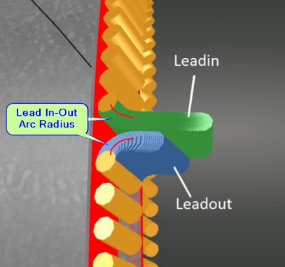 Lead In-Out Arc Radius = <distance>
This is the radius of the turn made by the leadin. Note that this is not the overall length of the leadin. Having this as a small radius decreases the range of gouging, but the tradeoff is that if it's too tight, the machine may fault or have difficulty making turn smoothly.
Leadin Steps = <integer number>
This is the number of steps PypeServer creates for the leadin. This adjustment is not typically made by the user.
Is Metric = <checkbox>
If you set this to Metric, all your machine and torch settings will be interpreted as metric. You can still have standard (Imperial) measurements parts. Note that you do not need to set this to Metric just because your machine runs in metric. This is only a convenience to allow users to work in familiar units.
Feedrate control adjustments
There are three settings to control feedrate, shown here:
These feedrate adjustments are combined to calculate a net feedrate for any given cutting step.
A and C axis feedrate control adjustments
The "A Rotate Feed Rate Increase" and "C Tilt Feed Rate Increase" settings allow you (or PypeServer support) to increase the feedrate of the machine in proportion to the speed of rotation of these axes. These settings are provided because some Vernon machines slow down more than the specified feedrate when the A and C axes are moving quickly. These fields can have two types of data:
A number, which works as a multiplier based on the rotation speed. For many Vernon 7000-series (machines with serial numbers in the 7000 range), an appropriate A Rotate Feed Rate Increase is 3, and an appropriate C Tilt Feed Rate Increase is 1.5.
These settings can also define a non-linear spline by points, where X is the rate of degrees per second, and Y is the desired feedrate multiplier at that rate. For example the A Rotate Feed Rate Increase may be set to:
"0,1,10, 1.5,40,3". This would provide a feedrate multiplication of one when the A-head is not rotating, and increase to 1.5x when the A-head is rotating at 10 degrees per second, and then ramping up to 3 when the A-head is rotating at 40 degrees per second.
Torch slowdown on tilt adjustment
The "C Bevel Feed Rate Decrease" field slows the head down as the torch leans over in beveling so as to compensate for cutting thicker material. A single number in this setting will defines a linear slowdown from no slowdown at zero degrees to the specified multiplier (slowdown) at 45 degrees.
Similar to the AC head feedrate multipliers, you can also enter a set of points to define a non-linear slow down ramp. For example: "0,1,15,0.9,30,0.7,45,0.6" would effect a non-linear progression through these feedrates:
0 tilt = 0 slowdown, 15 degrees = 0.9 of feedrate, 30 degrees = 0.7 of feedrate, 45 degrees = 0.6 of feedrate,
Default Smoothing Passes and Default Smoothing Distance Machine Settings
For best cutting on Vernon machines, the A-Head needs to rotate smoothly. Any rapid changes will result in the machine slowing down.
Also, for plasma torches, it is best to not rotate the torch through tight corners such that the torch stays in one place through the tight corner. This can occur in cuts such as an offset or tilted hole, a rectangle, or a y-trunk end-cut. To avoid this, the A-head rotation can be smoothed to effectively smooth transitions through areas where a true perpendicular torch cut would be less than optimal and typically over-burn.
The "Default Smoothing Distance" machine setting specifies the distance away from a given step that will be included in the smoothing algorithm. The higher the distance, the more each step is influenced by steps farther away. In some cuts, such as holes and rectangles, this setting can be overridden at the cut level by setting the Smoothing Distance for the cut.
The "Default Smoothing Passes" machine setting specifies how many passes the smoothing algorithm will run. The more smoothing passes, the smoother the A-head will rotate. However, in cases where directions change quickly, this will also increase the C-tilt from perpendicular across the pipe. For most cuts, 2 smoothing passes us sufficient. In some cuts, such as holes and rectangles, this setting can be overridden at the cut level by setting the Smoothing Passes for the cut.
Add Date Time To NC Files
When true, nc files will look like this: Part 96 11_30_21 17_50.nc
When false, nc files will look like this: Part 96.nc
Stagger Straight Cut Start Rotation Dist = <distance>
When straight cuts are nested together without any rotation between starts and finish, the leadins and leadouts can overlap and cause the torch to burn incorrectly or fault as the leadin torch start hits the leadin and leadout gaps of the previous cut. This instructs PypeServer nesting to rotate the next part by a distance (around the pipe) so as to avoid this intersection. Shown below is a 4.5" pipe with StaggerStraightCutStartRotationDist = 1 inch.
Torch Settings
General Tab
The Feedrate Decrease when Beveling field is described by the help button icon as follows:
The Dwell Seconds after Torch On field is described by the help button as follows:
The machine instructions can use Fineline torch cut tables by checking the Use Fineline Torch checkbox.
Tip Geometry Tab
The image below is the "Tip Geometry" tab of the Torch Settings
NOTE: By default, Vernon 5 Axis machines only use the Z axis to move to the Zero position that is programmed by Vernon customer support. The torch needs to be a give height off the pipe with the torch at its correct pivot height. This height has been seen to be 3/16" of an inch, though Vernon support can provide the required height. If your torch height is off after setting your pivot height, then you can either loosen the torch in the collet and raise it to the height specified by Lincoln, or contact Lincoln support, who can adjust the Z-zero height in machine settings.
If your machine cannot adjust Z on the fly (again, the default for Vernon machines) then this section does not apply.
Pause Machine for Torch Change for Fineline torches
As of this writing, Fineline torches cannot automatically change from Cut to Mark (Etch). Users can still create parts with both Plasma cuts and Etch marks.
Configure Torch Settings
Both Plasma and Etch torches must be configured to Pause for Torch Change.
Note: The machine will not pause for torch change on the first cut.
NC Code (what you will see)
Note: The machine will not pause for torch change on the first cut.
Use
When the machine pauses for a torch change, here (at the time of this writing) is where the change is made in the controller:
Swap Ground and Touch Sensor for Final Cuts
USER NOTE. This feature is still in development.
Initial Settings
SwapGroundAndSensorAtEnd = <True/False>
SwapGroundAndSensorAtEnd = True.
With the Vernon machine you can nest all the way to the far end of the pipe-through the "dead zone" where the ground is located and where the leading sensor needs something to touch-by
Pausing the machine,
Moving the ground to the trailing end of the final part,
Changing the torch height touch sensor from the leading to the trailing sensor.
PypeServer supports this in GCode by pausing the machine at the appropriate cut (step 1 above) and instructing the operator to swap the ground and torch height touch sensor. To enable this feature in PypeServer set the machine parameter SwapGroundAndSensorAtEnd = True. Seen in Machine Settings:
Part Requirements
This section describes requirements for the final part. Not all parts will work for this feature.
Your final part's first cut requiring this swap should be at least the distance from the torch tip to the trailing sensor, or there better be a piece of pipe for the machine to touch down on. Examples:
These will work. In both cases the trailing sensor can touch the trailing end of the final part.
These will not work. One solution for these scenarios is to use a longer part with enough space from the first cut in the dead-zone to the trailing end of the part. Another would be to leave the previous cut part in place such that the torch sensor can find that part, but you must make sure the sensor is not going to miss the pipe in a gap.
This may not always work. The operator must consider this scenario and check for this condition before starting any of the final cuts:
In this scenario, and the final cut is straight, user may consider rotating the pipe to get a sensor touch point.
Sample GCode
The following GCode for the following nesting:
Here's what you get before the start of the hole. The machine pauses and instructs you to swap the ground and sensor:
Here is what you get before the start of the final end-cut:
Setting the sensor
When instructed to set the sensor to the trailing sensor, you must set that manually in the Vernon machine software. Which end you set will depend on whether your machine is configured right or left-handed.
In WinMPM this will typically look like this:
In newer (VMD) versions the UI may look like this:
Related Articles
Calibrating the Vernon 5 Axis Machine
Calibrating the Vernon 5 Axis Machine Calibrating The Vernon MPM Machine This document covers the basics of making sure that your Vernon MPM machine is properly tuned and can cut parts as desired. Contents 1 Check machine tuning with WinMPM 2 2 Set ...LoneStar Machines Running Mach3
LoneStar Machines Running Mach3 PypeServer for Lone Star Machines Using Mach3 Controllers Table of Contents 1 General overview of network layout 2 2 PypeServer Settings Overview 3 2.1 Basic Machine Settings 3 2.2 Machine Properties 8 2.3 Torch ...PypeServer for the Vernon Mini
PypeServer for the Vernon Mini PypeServer for the Vernon Mini This is a user's manual for using PypeServer with the Vernon Mini. It covers configuring both PypeServer and the Vernon Mini so they work together. Contents 1 Training Materials 1 2 Vernon ...Pypeserver with EdgeConnect Machines
Pypeserver with EdgeConnect Machines PypeServer with EdgeConnect machines Machine configuration When configuring your machine, some preparatory steps are required in order to get meaningful test results. Getting axial directions correct This is done ...Getting Started with HGG Machines
Getting Started with HGG Machines PypeServer for HGG Machines This document covers topics specific to HGG machine working well with PypeServer. Topics include: General network layout for using PypeServer with the machine HGG ProCAM settings and ...